A worm gear transmits motion between two shafts crossed at 90° and gives a high ratio in a single stage. It is the heart of the worm reducers in conveyors, gates, mixers and lifting mechanisms. Below: how the worm and the worm wheel work, how the ratio is calculated, why some worm gears are self-locking and what they are made of.
What a worm gear is
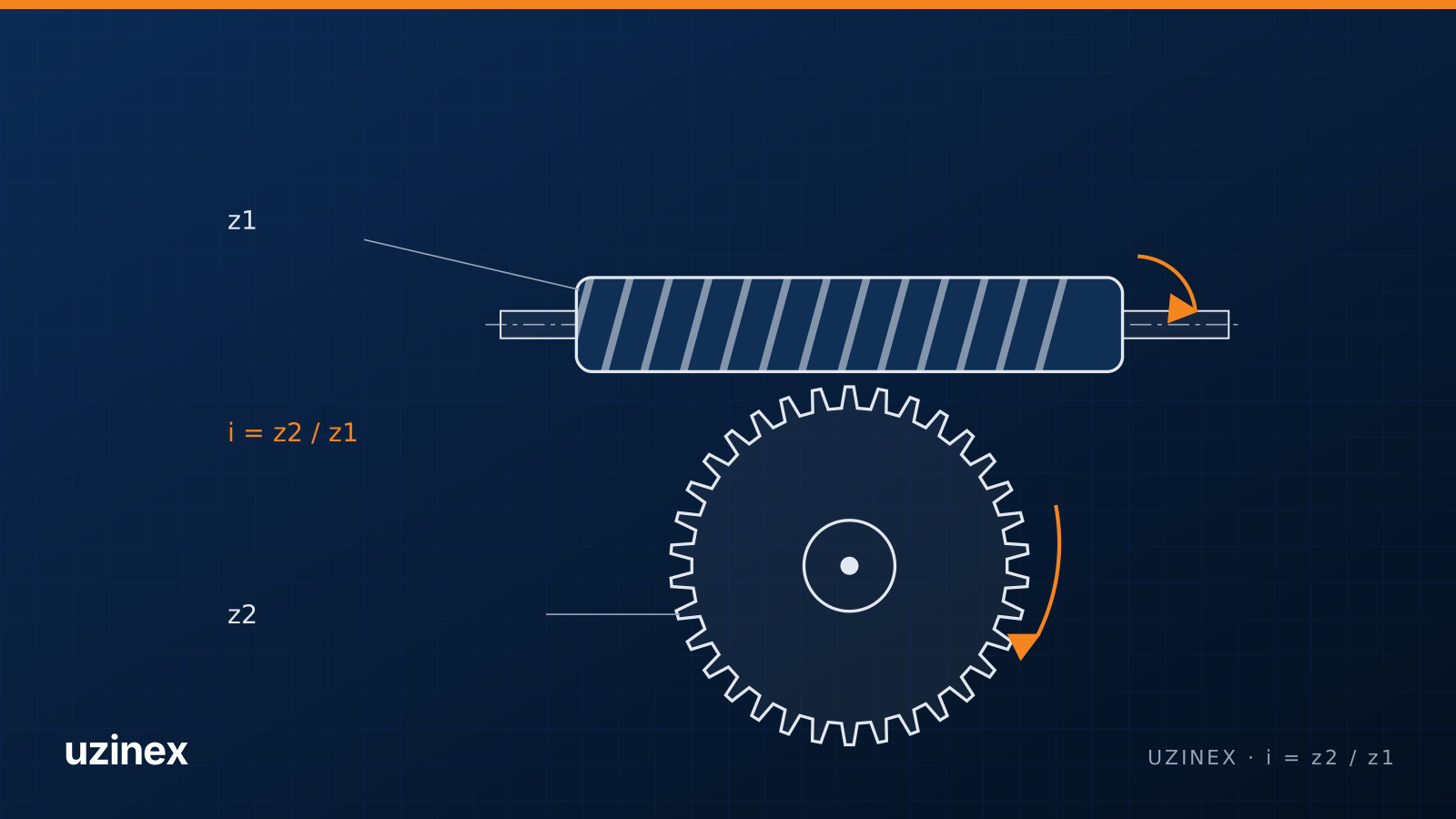
A worm gear has two parts: the worm, a shaft with a trapezoidal thread, and the worm wheel, a gear whose teeth are curved to wrap around the worm. The worm usually drives. With every turn its thread pushes the wheel teeth, and the wheel turns slowly on a perpendicular shaft.
Because the wheel teeth wrap around the worm, contact happens along a line rather than at a point. That allows high loads and smooth, shock-free running.
Worm gear ratio
The ratio is simple: i = z2 / z1, where z2 is the number of teeth on the worm wheel and z1 the number of starts on the worm (how many parallel threads it has). A single-start worm with a 40-tooth wheel gives 40:1, so the wheel makes one turn for every 40 turns of the worm.
Common single-stage ratios run from 5:1 to 100:1. Low ratios use worms with 2, 3 or 4 starts.
| Quantity | Formula |
|---|---|
| Gear ratio | i = z2 / z1 |
| Worm wheel pitch diameter | d2 = m · z2 |
| Worm pitch diameter | d1 = q · m (q is the diametral quotient, taken from tables) |
| Worm lead angle | tan γ = z1 / q |
| Centre distance | a = (d1 + d2) / 2 |
Why some worm gears are self-locking
When the worm lead angle is small, friction between thread and teeth stops the wheel from driving the worm backwards. The gear is then self-locking: the load stays in place without a brake. This usually happens with single-start worms and high ratios.
Self-locking depends on friction, and therefore on lubrication, vibration and wear. In lifting mechanisms, where a dropped load is dangerous, a worm reducer is always combined with a dedicated brake.
Worm gear efficiency
Sliding contact makes a worm gear lose more energy than a pair of cylindrical gears. Efficiency rises with the lead angle: single-start worms with high ratios can drop below 50%, while multi-start worms exceed 80–90%. Losses turn into heat, which is why worm reducer housings have cooling fins and the oil is chosen carefully.
Worm and worm wheel materials
- The worm is made of hardened and ground steel, usually a case-hardening steel (16MnCr5) or a through-hardening steel (42CrMo4) with hardened flanks. A smooth thread surface reduces friction.
- The worm wheel is made of tin bronze, for example CuSn12, centrifugally cast onto a steel or cast iron hub. The bronze, softer than the worm, runs in against it and takes the sliding without seizing.
- For light loads and low speeds, cast iron or engineering plastic wheels are also used.
Lubrication matters a lot: synthetic oils (polyalphaolefins or polyglycols) compatible with bronze are recommended for worm gears, as they reduce friction and temperature.
How a worm wheel is made
A worm wheel is hobbed with a hob that has exactly the profile of the mating worm, on a gear hobbing machine. The hob feeds radially or tangentially into the blank, and the teeth come out curved to the worm. The worm itself is turned or milled, then hardened and ground.
On a CNC gear hobbing machine, a worm wheel is cut on the same machine as cylindrical gears: only the hob and the program change. One workshop working on such a machine is Miatec in Pechea, Galați County, Romania; see the gear hobbing machine case study.
Where worm reducers are used
- belt and screw conveyors, elevators, mixers;
- automatic gates, barriers, opening mechanisms;
- lifting and positioning mechanisms, with a brake;
- farm machinery: seed drills, spreaders, feed mixers;
- rotary tables and dividing heads, where low backlash matters.
Common failures
The most common are bronze wheel wear, scoring under poor lubrication, flank pitting and overheating. The usual cause is the wrong or degraded oil. A worn worm wheel is replaced together with the worm, so the new pair runs in correctly.
Frequently asked questions
How do you calculate a worm gear ratio?
Divide the number of teeth on the worm wheel by the number of starts on the worm. A 30-tooth wheel with a single-start worm gives 30:1; the same wheel with a two-start worm gives 15:1.
What is a multi-start worm?
A worm with several parallel threads, like a multi-start screw. For every turn, the wheel advances as many teeth as the worm has starts. The ratio drops and the efficiency rises.
Why is the worm wheel made of bronze?
The contact between worm and wheel involves a lot of sliding. Bronze, softer than the hardened worm, runs in against it, holds oil on its surface and resists seizing.
Is every worm reducer self-locking?
Self-locking only appears at small lead angles, usually with single-start worms, and depends on friction. For lifted loads a separate brake is used.
How is a replacement worm wheel made?
On a gear hobbing machine, with a hob that matches the profile of the mating worm. For a part copied from a sample, what matters is the module, the number of teeth, the number of worm starts and the thread hand.