Gears carry motion and torque in almost every machine: reducers, gearboxes, pumps, farm machinery, lifting gear. This guide covers the main types of gears, what the module and the diameters mean, which materials are used, how gears are made and what to measure when you replace a worn gear.
What a gear is and what a gear train is
A gear is a wheel with teeth cut around its rim that transmits motion through direct tooth contact with another gear. Two or more gears working together form a gear train (a gear pair or mesh). The smaller gear in a pair is called the pinion, the larger one the gear or wheel.
Compared with belts and chains, a gear drive transmits high torque in a small space, keeps an exact ratio without slip and is highly efficient, usually above 95% per stage for well-made cylindrical gears.
Types of gears
The gear type follows the position of the shafts and the load. The table summarises the types used most often.
| Type | Shaft position | What sets it apart | Where it is used |
|---|---|---|---|
| Spur gears | parallel | simple, low cost, no axial force; noisier at high speed | reducers, gearboxes, pumps, mechanisms |
| Helical gears | parallel | teeth engage gradually, quiet running, higher load; creates axial force | industrial reducers, car and tractor gearboxes |
| Double helical (herringbone) gears | parallel | two opposite helices cancel the axial forces | heavy drives, rolling mills, turbines |
| Bevel gears | intersecting, usually at 90° | change the direction of motion; straight or spiral teeth | differentials, right-angle drives, farm machinery |
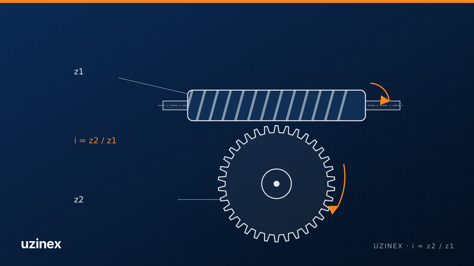
| Worm gears (worm and worm wheel) | crossed at 90° | high ratio in one stage, quiet, can be self-locking | worm reducers, gates, conveyors, hoists |
| Rack and pinion | rotation to translation | turns rotation into linear motion | sliding gates, CNC machines, steering |
| Internal gears | parallel, coaxial | teeth on the inside of a ring; the basis of planetary gearboxes | planetary reducers, automatic transmissions |
Sprockets are a separate family: they mesh with a chain, not with another gear, have a different profile and are cut with dedicated tools.
Gear module and gear diameters
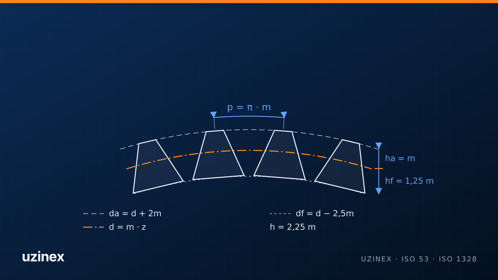
The module (m) describes tooth size: it is the pitch diameter divided by the number of teeth. Two gears mesh correctly only with the same module and the same pressure angle. The module and the number of teeth (z) give all the main dimensions:
- pitch diameter: d = m · z;
- tip (outside) diameter, measured across the tooth tips: da = d + 2m;
- root diameter, at the bottom of the tooth spaces: df = d − 2.5m;
- circular pitch between two teeth: p = π · m;
- whole depth of the tooth: h = 2.25m;
- centre distance of two gears: a = m · (z1 + z2) / 2.
Example: a module 2 gear with 30 teeth has a 60 mm pitch diameter and a 64 mm tip diameter. You can work out all of these, plus the gear ratio and the span measurement, in the gear calculator. For standard modules and how to find the module of a gear without a drawing, see gear module: formulas and module chart.
Involute profile and pressure angle
Gear tooth flanks have an involute shape, the curve traced by the end of a string unwound from a circle (the base circle). The involute has two practical advantages: the ratio stays constant, and the mesh tolerates small centre distance errors without losing its function.
The standard pressure angle is 20° (ISO 53). Older machines still have 14.5° gears, and some heavily loaded drives use 25°. Gears with different pressure angles do not mesh with each other, even with the same module.
Gear materials
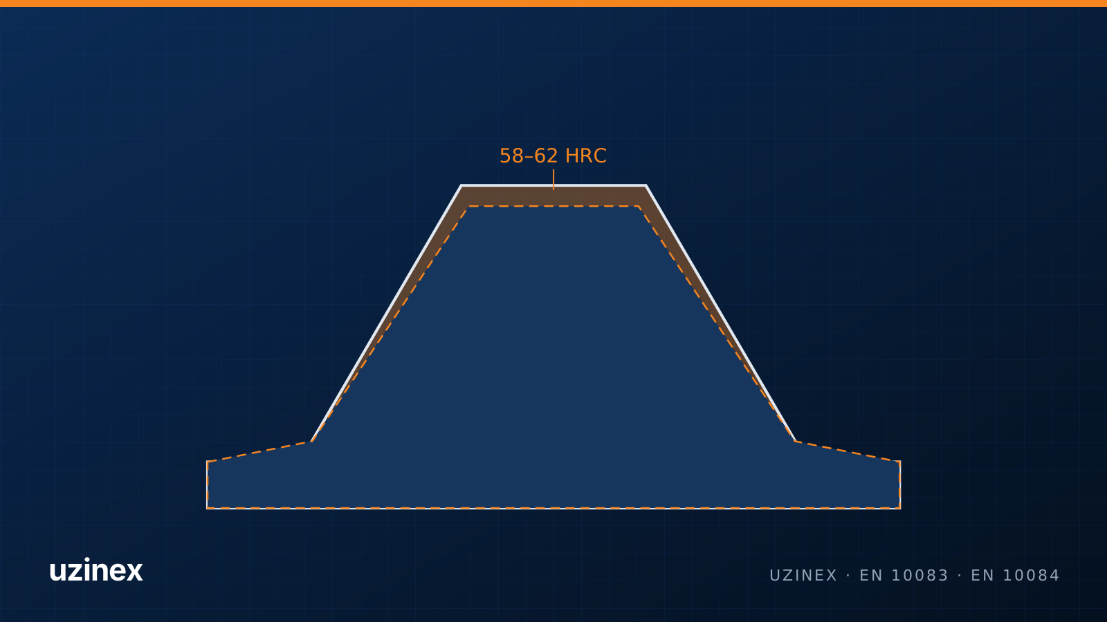
Metal gears are usually made of steel. Through-hardening steels such as 42CrMo4 and C45 are used for moderate to high loads, optionally with induction-hardened flanks. Case-hardening steels such as 16MnCr5 and 20MnCr5 give a hard surface layer and a tough core, ideal for loaded gearboxes and reducers. Worm wheels are made of bronze, large slow gears of cast iron, and quiet light-duty gears of engineering plastics (POM, PA6).
The detailed comparison, with heat treatments and hardness, is in 42CrMo4 vs 16MnCr5 vs C45: choosing gear steel.
How gears are made
The blank is turned to its outside diameter, bored and, if needed, heat treated. Then the teeth are cut with one of these processes:
- Gear hobbing: the hob and the workpiece rotate in sync and the teeth are generated by rolling. It is the most productive process for external cylindrical gears, worm wheels and splines. On a CNC gear hobbing machine, moving to a new gear means a new program and a new hob.
- Gear shaping: a reciprocating pinion-type cutter, used for internal gears and for gears with a shoulder close to the teeth.
- Form milling with a module cutter: space by space on a dividing head; suitable for one-offs and repairs.
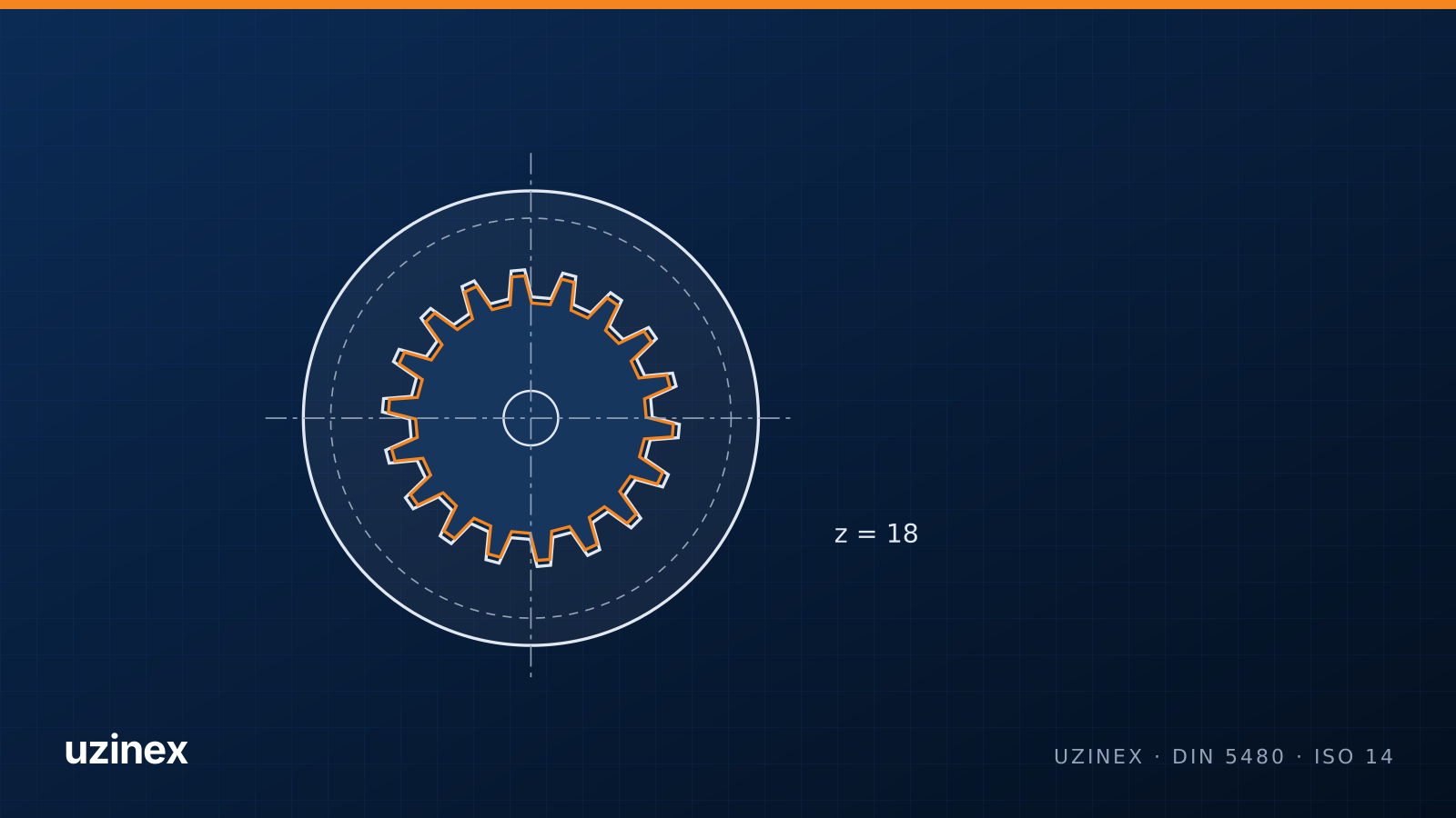
- Broaching: for internal teeth and splines in large batches.
- Grinding and shaving: finishing operations after heat treatment, for high accuracy and low noise.
A real example: a farmer from Pechea, Galați County, Romania, opened a workshop through his company Miatec that makes gears on a CNC gear hobbing machine with a Siemens Sinumerik 828D, with EU funding through AFIR. The full story, with technical data, is in the case study.
Gear accuracy grades
Gear accuracy is expressed in grades under ISO 1328 (or DIN 3961/3962 in older documents); AGMA 2015 uses a similar scale. A lower number means higher accuracy. Hobbed gears usually reach grades 7–9, ground gears grades 3–6. Grade 7 is typical for industrial reducers, farm machinery gearboxes and pumps.
How to replace a worn gear
To make a replacement gear from a sample, record or measure:
- the number of teeth;
- the tip diameter, with calipers across the tooth tips;
- the tooth type: spur or helical, and for helical gears the helix angle and hand (left or right);
- the face width and the bore, keyway or spline dimensions;
- the material and hardness, if they can be found.
For a spur gear with no profile shift, the module is the tip diameter divided by the number of teeth plus 2: m = da / (z + 2). The gear calculator does this and suggests the nearest standard module. To confirm it, measure the span over teeth with a disc micrometer.
Frequently asked questions
What are the main types of gears?
Spur and helical gears (parallel shafts), bevel gears (intersecting shafts), worm gears (crossed shafts), rack and pinion, and internal gears used in planetary gearboxes.
What is the module of a gear?
The module is tooth size in millimetres: the pitch diameter divided by the number of teeth. Gears that mesh together have the same module.
What are metal gears made of?
Most often through-hardening steels (42CrMo4, C45) or case-hardening steels (16MnCr5, 20MnCr5). Worm wheels are made of bronze, and large slow gears of cast iron.
What is the difference between spur and helical gears?
Helical teeth engage gradually, so the gear runs quieter and carries more load, but they create an axial force the bearings must take. Spur gears are simpler to make and put no axial load on the bearings.
How are gears made?
Most often by gear hobbing on a gear hobbing machine. Internal gears are made by shaping or broaching, and high-precision gears are ground after heat treatment.