The module is the first number that matters on a gear: the diameters, the pitch, the tooth depth and the centre distance all follow from it. This guide explains what the gear module is, how to calculate it, how to find the module of a gear with no drawing and which standard modules are used, with a working gear module chart.
What the module of a gear is
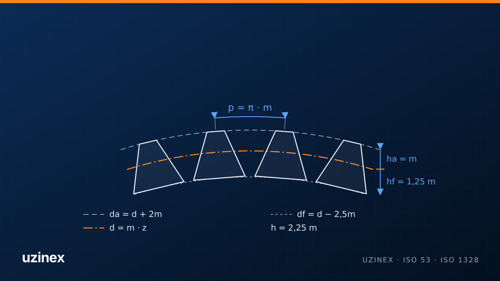
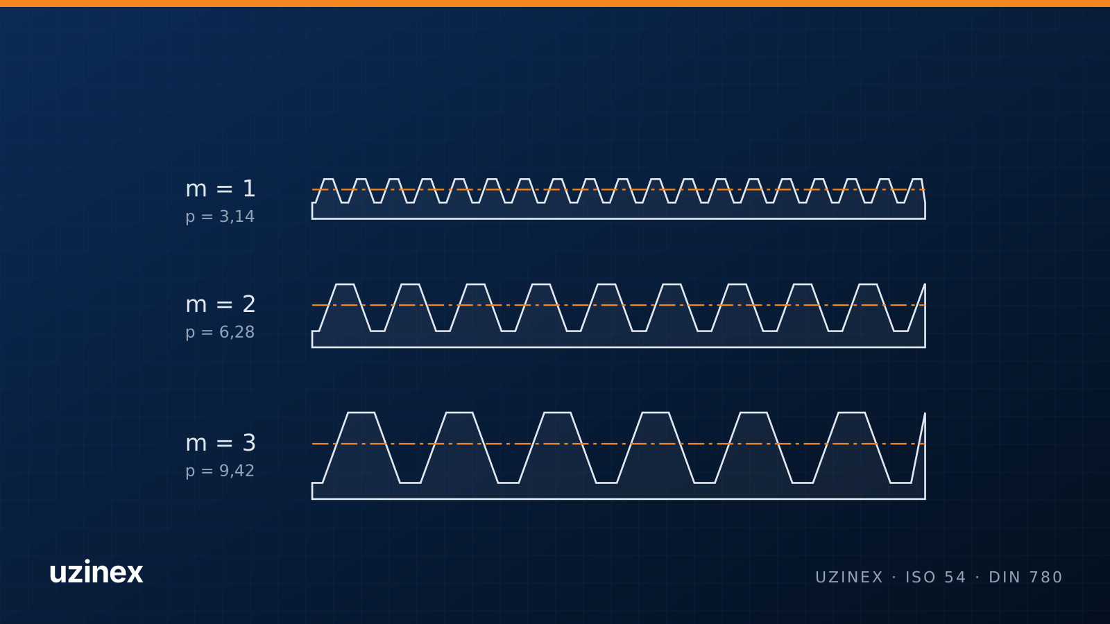
The module (m) is the pitch diameter divided by the number of teeth: m = d / z. Put another way, it is the circular pitch divided by π: m = p / π. It is given in millimetres and describes tooth size: a module 3 gear has teeth three times larger than a module 1 gear.
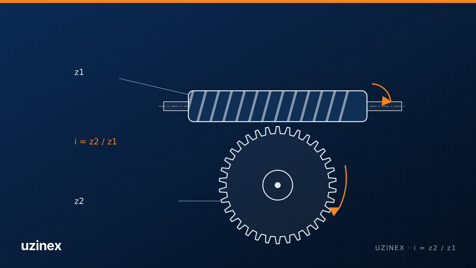
The basic rule: two gears mesh correctly only with the same module and the same pressure angle. The tooth counts can differ; their ratio gives the gear ratio.
Formulas that start from the module
| Quantity | Formula (spur gears, ISO 53 profile) | Example: m = 2, z = 30 |
|---|---|---|
| Pitch diameter | d = m · z | 60 mm |
| Tip (outside) diameter | da = m · (z + 2) | 64 mm |
| Root diameter | df = m · (z − 2.5) | 55 mm |
| Circular pitch | p = π · m | 6.283 mm |
| Addendum | ha = m | 2 mm |
| Dedendum | hf = 1.25 · m | 2.5 mm |
| Whole depth | h = 2.25 · m | 4.5 mm |
| Tooth thickness on the pitch circle | s = π · m / 2 | 3.142 mm |
| Centre distance (with a z2 = 45 gear) | a = m · (z1 + z2) / 2 | 75 mm |
For helical gears, the module is given in the plane normal to the tooth (the normal module mn). The diameters use the transverse module mt = mn / cos β, where β is the helix angle. The gear calculator does all of these calculations automatically.
Gear module chart
Modules are standardised so that hobs, gauges and gears fit together. ISO 54 recommends series I; series II is used only when series I does not fit. Below 1 mm, the fine modules of DIN 780 are used.
| Module (mm) | Circular pitch π·m (mm) | Whole depth 2.25·m (mm) | Diametral pitch 25.4/m |
|---|---|---|---|
| 0.5 | 1.571 | 1.125 | 50.80 |
| 0.6 | 1.885 | 1.350 | 42.33 |
| 0.7 | 2.199 | 1.575 | 36.29 |
| 0.8 | 2.513 | 1.800 | 31.75 |
| 0.9 | 2.827 | 2.025 | 28.22 |
| 1 | 3.142 | 2.250 | 25.40 |
| 1.25 | 3.927 | 2.813 | 20.32 |
| 1.5 | 4.712 | 3.375 | 16.93 |
| 2 | 6.283 | 4.500 | 12.70 |
| 2.5 | 7.854 | 5.625 | 10.16 |
| 3 | 9.425 | 6.750 | 8.47 |
| 4 | 12.566 | 9.000 | 6.35 |
| 5 | 15.708 | 11.250 | 5.08 |
| 6 | 18.850 | 13.500 | 4.23 |
| 8 | 25.133 | 18.000 | 3.17 |
| 10 | 31.416 | 22.500 | 2.54 |
| 12 | 37.699 | 27.000 | 2.12 |
Series II: 1.125, 1.375, 1.75, 2.25, 2.75, 3.5, 4.5, 5.5, 7, 9, 11, 14, 18, 22, 28, 36, 45.
How to find the module of a gear with no drawing
- Count the teeth (z). Mark one tooth with paint so you do not lose count.
- Measure the tip diameter (da) with calipers. With an even number of teeth, measure tip to tip; with an odd number, measure from one tip to the bottom of the opposite space and add the tooth depth, or use the bore as a reference.
- Calculate: m = da / (z + 2). Example: 18 teeth and a 40 mm tip diameter give m = 40 / 20 = 2.
- Round to the nearest standard module in the chart. If the result falls between two values, the gear may be profile-shifted, worn or imperial.
- Check with a module gauge or with a span measurement taken with a disc micrometer.
If the value matches no metric module, try imperial: diametral pitch DP = (z + 2) / da, with da in inches. Gears on American or British machines are often DP 8, 10, 12 or 16.
Module, diametral pitch and circular pitch
In the imperial system tooth size is given by diametral pitch (DP), the number of teeth per inch of pitch diameter. The conversion is m = 25.4 / DP. Circular pitch (CP) is the pitch measured on the pitch circle, in inches: CP = π / DP.
| Diametral pitch | Equivalent module (mm) | Nearest metric module |
|---|---|---|
| DP 4 | 6.350 | 6 |
| DP 6 | 4.233 | 4 |
| DP 8 | 3.175 | 3 |
| DP 10 | 2.540 | 2.5 |
| DP 12 | 2.117 | 2 |
| DP 16 | 1.588 | 1.5 |
| DP 20 | 1.270 | 1.25 |
Close values are not interchangeable: a DP 10 gear (2.54) running with a module 2.5 gear wears quickly and is noisy.
How the module is chosen in design
The module is sized from the transmitted torque, the material, the face width and the tooth count, through the tooth root bending and flank contact stress calculations (ISO 6336 or DIN 3990). As a reference: modules 1–3 appear in pumps, mechanisms and small reducers, 3–6 in industrial reducers and gearboxes, and above 8 in heavy drives.
Production also depends on tooling: every module needs its own hob. A workshop running a CNC gear hobbing machine builds its hob set around the modules its customers ask for most; Miatec in Pechea, Romania, presented in the case study, works with modules from 0.1 to 3.
Frequently asked questions
How do you calculate the module of a gear?
Divide the pitch diameter by the number of teeth: m = d / z. If you only have the gear, use the tip diameter: m = da / (z + 2), for spur gears with no profile shift.
What standard gear modules exist?
ISO 54 series I: 1, 1.25, 1.5, 2, 2.5, 3, 4, 5, 6, 8, 10, 12, 16, 20, 25, 32, 40, 50. Below 1 mm, the fine modules of DIN 780, for example 0.5, 0.6, 0.8.
Can gears with different modules mesh?
No. Gears that work together share the same module and the same pressure angle.
How do I convert diametral pitch to module?
The module is 25.4 divided by the diametral pitch. DP 10 means module 2.54, and DP 8 means module 3.175.
What is the pitch diameter of a gear?
The circle on which two gears roll on each other without slipping. It is the module times the number of teeth and sets the centre distance.