
The gear pump is the most widespread hydraulic pump: you find it on tractors, construction machinery, presses, machine tools and in lubrication systems. It is simple, compact and inexpensive, but it only works well if its gears are made precisely. This guide explains how a gear pump works, how to calculate its flow and what its gears need.
How a gear pump works
An external gear pump has two identical gears meshing in a housing with very tight clearances. One gear is driven by the motor, the other turns in mesh with it.
- Suction: where the teeth come out of mesh, the volume between them grows and creates a vacuum, so fluid enters the pump.
- Transport: the fluid is trapped in the spaces between the teeth and the housing wall and carried around the outside of the gears, from suction to discharge.
- Discharge: where the teeth come back into mesh, the volume shrinks and the fluid is pushed out under pressure.
The fluid does not pass between the gears through the middle: the meshing teeth form a seal between suction and discharge. That is why the sealing between tooth tips and housing, and between gear faces and side plates, decides how well the pump holds pressure.
Types of gear pumps
| Type | Construction | What sets it apart | Where it is used |
|---|---|---|---|
| External gear pump | two equal spur gears in a figure-eight housing | simple, robust, low cost; moderate noise | tractors, mobile machinery, presses, power units |
| Internal gear pump with crescent | a pinion meshing inside a ring gear, with a crescent-shaped separator | quiet, low pulsation, high pressure | machine tools, injection moulding machines, stationary hydraulics |
| Gerotor | inner rotor with one tooth fewer than the outer rotor | compact, no separator | engine and gearbox lubrication, hydraulic motors |
How to calculate gear pump flow
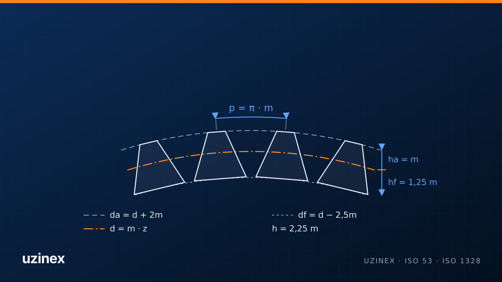
The volume pumped per revolution (displacement) of an external gear pump is approximated by V ≈ 2 · π · m² · z · b, where m is the module, z the number of teeth on one gear and b the face width. The actual flow is Q = V · n · ηv, with n the speed and ηv the volumetric efficiency.
Example: gears with module 2 mm, 12 teeth and 20 mm face width give a displacement of about 6 cm³/rev. At 1,500 rpm and 90% volumetric efficiency, the flow is about 8 l/min. You can check gear module and face width quickly with the gear calculator.
External gear pumps usually work up to 250–300 bar, with volumetric efficiencies of 85–95% when new. As clearances grow with wear, efficiency drops and the pump heats the oil.
What gear pump gears need
- Few teeth and a corrected profile: pump gears usually have 9 to 14 teeth, for a large displacement in a small size. Below the undercut limit, the teeth are cut with positive profile shift to stay strong.
- A precise tip diameter: the clearance between tooth tips and housing is a few hundredths of a millimetre. The tip diameter is ground.
- Accurate flanks: profile errors increase pulsation, noise and leakage. Pump gears are hobbed and ground, usually to ISO 1328 grades 5–7.
- Flat, parallel faces: side sealing happens on the gear faces, so flatness and width have tight tolerances.
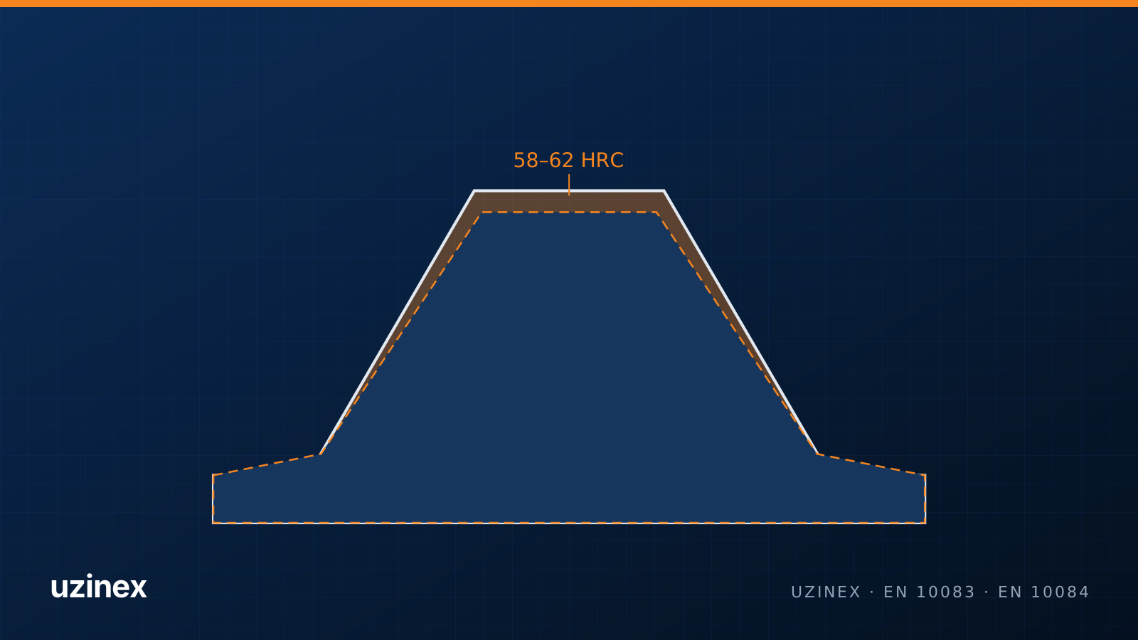
- A hard material: a case-hardening steel such as 16MnCr5, carburized and hardened to 58–62 HRC, for wear resistance; more in choosing gear steel.
Common failures and causes
- Housing and gear wear from contaminated oil: flow drops and the pump runs hot.
- Cavitation from a restricted suction or oil too viscous when cold: metallic noise and pitting on the flanks.
- Broken teeth from overpressure or foreign bodies.
- Side plate and bushing wear, which increases internal leakage.
When a pump no longer holds pressure, the gear set is replaced and, where needed, the side plates or the housing. For older pumps on farm machinery, replacement gears are made from a sample on a gear hobbing machine.
Pump gears made locally
Pump gears are among the parts made by the Miatec workshop in Pechea, Galați County, Romania, on a CNC gear hobbing machine with a Siemens Sinumerik 828D, bought with EU funding through AFIR. The machine works from 3 teeth up, with modules from 0.1 to 3, which suits most pumps on farm machinery. The full story is in the case study.
Frequently asked questions
How does a hydraulic gear pump work?
Two meshing gears turn in a tight housing. Fluid enters where the teeth come out of mesh, is carried around the outside of the gears in the tooth spaces and is pushed out where the teeth come back into mesh.
What pressure can a gear pump deliver?
External gear pumps usually work up to 250–300 bar. Internal gear pumps reach higher pressures with lower pulsation.
How do I calculate gear pump flow?
Displacement is approximately V ≈ 2 · π · m² · z · b. Flow is displacement times speed times volumetric efficiency.
Why does a gear pump lose pressure?
Most often from wear on the gears, housing or side plates, which opens up clearances and internal leakage. Contaminated oil and cavitation speed up the wear.
Can replacement gears be made for an old pump?
Yes. A gear hobbing machine makes gears from a sample: you measure the number of teeth, tip diameter, face width and shaft, establish the module, then the gears are hobbed, heat treated and ground.